-
Lithium-ion batteries – electrolytes – solid & semi-solid
-
Li2.2Ta1.0O1.6Cl3.8H0.11 was synthesized under argon (dew point ≤ -60°C) from Li2O,
LiOH and TaCl5 through grinding in an agate mortar, followed by a heat treatment (350°C, 3 h), followed by further grinding in an agate mortar.
The resulting material was allowed to stand for 30 min in an atmosphere with a dew point of -30°C, which resulted in the formation of
Li2.2Ta1.0O1.6Cl3.8H0.11 with an ion conductivity of 4.2 × 10⁻³ S/cm.
After another heat treatment (300 °C, 3 h), the resulting material exhibits an ion conductivity of 5.2 × 10⁻³ S/cm.
This work illustrates how very hygroscopic oxohalide materials that contain a carefully controlled quantity of protons exhibit
very favorable ion conductivity.
It will be very interesting to see if the employment of a minor amount of protons with carefully controlled mobility and reactivity in cells
allows for improved overall performance in solid-state Li-ion battery cells (avoidance of parasitic reactions caused by protons).
-
The premium version includes another two patent discussions, plus an Excel list with 50-100 commercially relevant recent patent families.
-
Get a quote to make better informed decisions.
-
Lithium-ion batteries – positive electrode
-
Ni0.96Co0.02Mn0.02(OH)2
was produced via the coprecipitation method from aqueous solutions of nickel sulfate, cobalt sulfate, and manganese sulfate.
This hydroxide was then heated at 650°C for 5 h in air to form a metal composite oxide.
An aqueous solution of Li2Si5O11 was combined with this oxide.
The slurry was then heated under vacuum, followed by mixing with lithium hydroxide and firing at 720°C,
resulting in Li1.06Ni0.96Mn0.02Co0.02Si0.03OX (X: not disclosed)
with Si-containing pores.
In half-cell tests, the material exhibits a capacity retention of 95.7% (after 50 cycles, 0.5 C charge / 1 C discharge)
as compared to 77.9% for a comparative material without Si.
This work illustrates how the incorporation of Li2Si5O11 into high-nickel NMC leads to improved
cycling stability.
As described in the patent filing, materials with lower Si content (such as
Li1.06Ni0.96Mn0.02Co0.02Si0.01OX, X: not disclosed) also exhibit improved
cycling stability as compared to the comparative example, while exhibiting improved high rate characteristics.
-
The premium version includes another two patent discussions, plus an Excel list with 50-100 commercially relevant recent patent families.
-
Get a quote to make better informed decisions.
-
Lithium-ion batteries – negative electrode (excluding Li metal electrodes)
-
A continuous process for the production Si-carbon composite active materials in which nanosized pores in
porous carbon
are filled with Si is described that
consists of 3 major process steps:
-
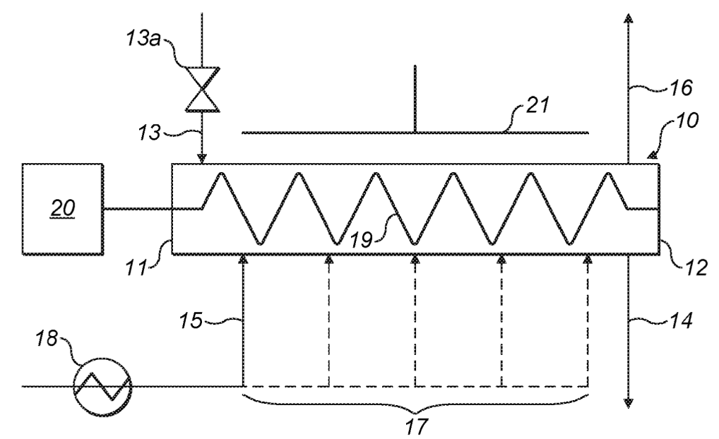
Chemical vapor infiltration (CVI) of porous carbon with silane gas to deposit carbon at about 370°C / 1 bar (see top Figure). This step is not
straightforward because it has to be assured that pores are homogeneously penetrated for homogeneous Si
deposition. This was achieved in the reactor shown below by controlling the rate of introduction and removal of
reactants along with the speed at which reactants move in the reactor. Reactant gas can be introduced through
intermediate gas inlets 17 (assurance of uniform silane gas concentration) and an auger conveyor was employed
(may additionally contain radial mixing elements).
-
Coating with a carbon layer (chemical vapor deposition, CVD, about 500°C / 1 bar).
-
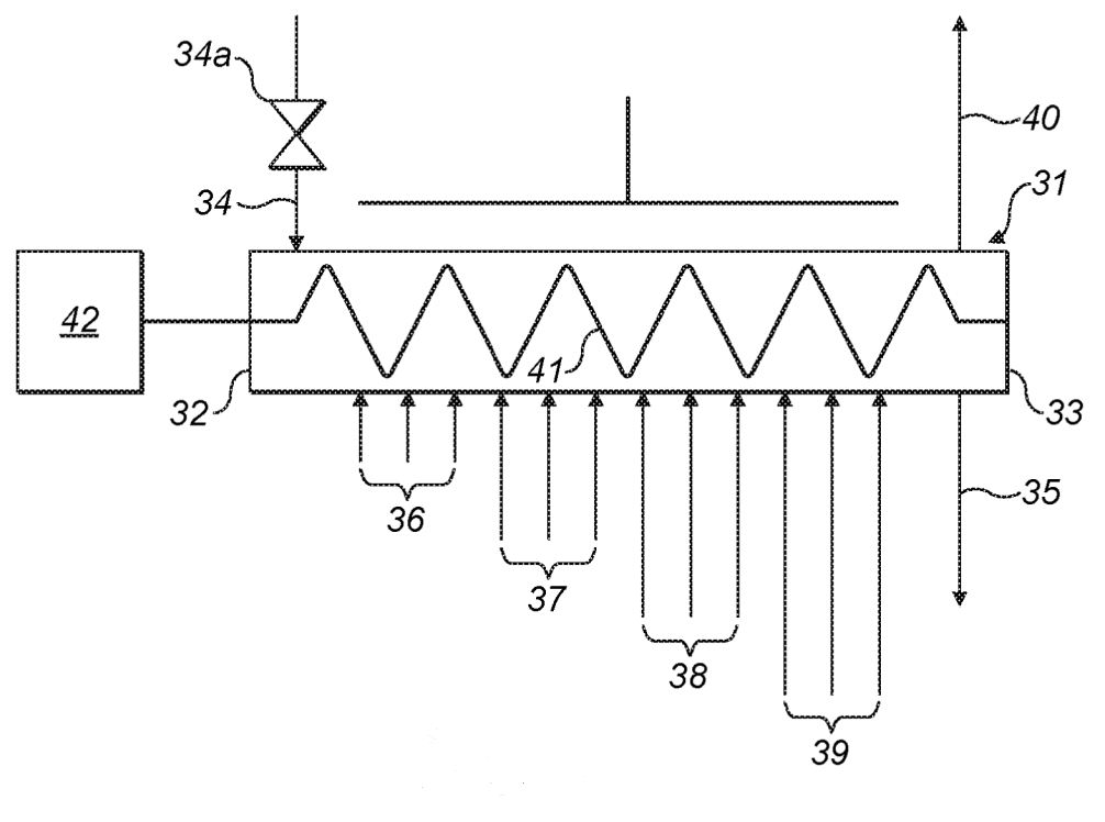
Passivation with dry air (see bottom Figure, about 150 °C / 1 bar).
The oxygen content is maintained steady across the oven
by introducing additional oxygen in inlet groups 36-39.
10: continuous tubular reactor, 11: first end, 12: second end, 13: particle inlet, 13a: airlock valve, 14: particle outlet,
15: gas inlet, 16: gas outlet, 17: additional gas inlet, 18: gas heater, 19: auger, 20: electric motor, 21: electric heater

30: passivation unit, 31: tubular reactor, 32: first end, 33: second end, 34: particle inlet, 34a: airlock valve,
35: particle outlet, 36, 37, 38, 39: inlet groups, 40: gas outlet, 41: auger, 42: electric motor

This work illustrates how it is crucial in continuous silane gas deposition and carbon passivation processes to maintain a homogeneous
concentration of reactant gas (silane or oxygen) across the reactor.
Since Nexeon made an
agreement with Panasonic
to start supplying its Si-carbon active material from 2025 from a new plant in Kentucky,
it can be assumed that cost-effective upscaling has been substantially validated within the frame of this collaboration.
-
The premium version includes another two patent discussions, plus an Excel list with 50-100 commercially relevant recent patent families.
-
Get a quote to make better informed decisions.
-
Fuel cells (PEMFC / SOFC / PAFC / AEMFC) – electrochemically active materials
-
Two distinct catalyst slurries were used to coat the PEM (proton exchange membrane) with a catalyst bilayer:
First layer (faces PEM):
-
Average particle size of the first platinum catalyst: ≤2 nm.
-
Carbon type: Vulcan X72 (specific surface area of the first carbon carrier: about 900 m2/g).
-
I/C (ionomer/carbon) ratio: about 1.
-
Ratio (platinum catalyst / (platinum catalyst + carbon): about 55%.
-
EW (equivalent weight, polymer weight that corresponds to 1 mol exchangeable protons): about 900 g/mol.
Second layer (on top of first layer):
-
Average particle size of the first platinum catalyst: about 4 nm.
-
Carbon type: graphitized carbon (specific surface area of the first carbon carrier: about 150 m2/g).
-
I/C (ionomer/carbon) ratio: ≤0.8.
-
Ratio (platinum catalyst / (platinum catalyst + carbon): about 30%.
-
EW (equivalent weight, polymer weight that corresponds to 1 mol exchangeable protons): about 760 g/mol.
An accelerated aging test was carried out by applying a dynamic voltage of 0.6-0.95 V on the cathode (2 s cycle time) for 30,000 cycles.
The above structure with the bilayer catalyst exhibits an ECSA (electrochemically active surface area) reduction of 30% in this test,
as compared to >40% for a comparable example with
a monolayer catalyst (3 nm average catalyst particle size, 800 m2/g specific surface area of carbon, I/C ratio 0.9).
This work illustrates how the optimized catalyst structure is different near the PEM as compared to the
outer edge of the catalyst layer. Optimal structure near PEM: 1) low catalyst particle size,
2) high carbon specific surface area, 3) high catalyst loading,
4) high exchangeable proton density.
-
The premium version includes another two patent discussions, plus an Excel list with 50-100 commercially relevant recent patent families.
-
Get a quote to make better informed decisions.
-
Triweekly patent lists for other categories (Excel files are included for premium users)
-
- Lithium metal containing batteries (excluding Li-S, Li-Air): XLSX
-
- Lithium-ion batteries – electrolytes – liquid: XLSX
-
- Lithium-ion batteries – separators: XLSX
-
- Lithium-sulfur batteries: XLSX
-
- Metal-air batteries: XLSX
-
- Na-ion batteries: XLSX
-
Prior patent updates
-
2023-10-10
-
2023-09-19
|