-
Lithium-ion batteries – electrolytes – solid & semi-solid
-
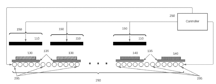
A sintering apparatus is described (see Figure below), employing a rapid thermal processing (RTP) method,
with a furnace heated between 1,050°C and 1,250°C for 30 s to 3 min.
The green tape (binder-containing oxide film precursor), cast on a metal foil, was laser-cut,
and stacked between setter components (135) on a bottom graphite heating plate,
with a top graphite plate (110) positioned closely above.
Setter components (135) consist of a dense Al2O3 plate on which the green sheet (130) lays
(on a metal support, for example W, Ni, Mo-based), surrounded by a ceramic or metal frame and another Al2O3 plate on top.
The assembly was heated to 800°C at a ramp rate of 50°C/min to 100°C/min, held for 5 min with an argon gas flow,
and then heated to 1,100°C at a ramp rate of 100°C/min to 300°C/min for sintering. After 30 s,
it was cooled to room temperature at 100°C/min to 300°C/min. The furnace contains multiple zones with heating elements (110).
Materials move on a conveyor at 2-8 cm/min through zones.
The processed materials, like solid-state electrolyte or lithium-stuffed garnet,
exhibit a pre-sintering thickness around 100 μm and post-sintering thickness between 10 μm and 30 μm.
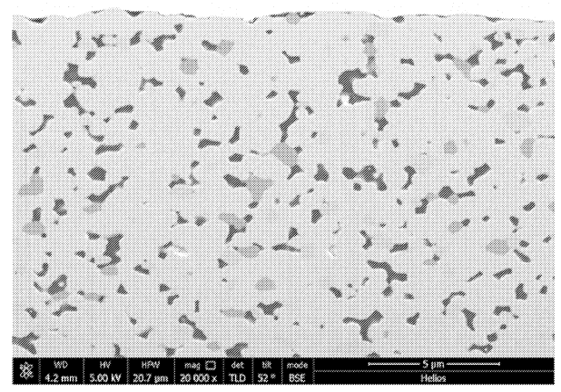
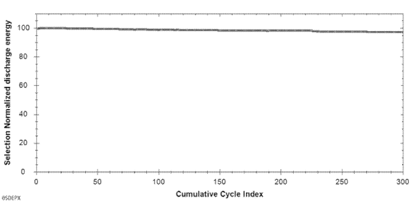
Further Figures below include a SEM image of the solid electrolyte layer and cycling data (6-layer cells,
lithium metal negative electrodes, NMC-based positive electrodes, liquid catholyte that contains lithium salt, 1.35 C charge, 1 C discharge, 25°C,
1 atmosphere).
110: heating element
130: green sheet (precursor of solid electrolyte layer)
135: setter
140: sintered element
150: separate zone
250: controller
290: conveyor
295: roller


This work illustrates efforts towards high-throughput sintering of oxide films, with film imperfections
carefully balanced to minimize costs without negatively impacting electrochemical longevity.
The throughput rate of 2-8 cm/min is substantially lower as compared to currently used Li-ion battery electrode coating processes.
-
Lithium-ion batteries – positive electrode
-
A tank reactor was filled with deionized water at 55°C and the pH was adjusted to 8.05 using sodium hydroxide.
A co-precipitation reaction was initiated by feeding an aqueous solution of Ni and Mn sulfates (1:2 molar ratio, 1.65 mol/kg) and a 27 mass% sodium carbonate solution.
With a continuous feed system, a transition metal carbonate precursor was produced, filtered, washed, dried at 120°C, and sieved.
The resulting material was combined with Li2CO3 (Li / transition metal molar ratio of 1.30), heated to 930°C for 5 h under a gas mix of 20% oxygen and 80% nitrogen, and sieved through a 32 µm mesh.
SnSO4 (3.0 mass% with respect to uncoated positive electrode active material) was dispersed in deionized water via sonication.
The material prepared in the prior step was added, sonicated further, then stirred for 3 h. Water was removed under vacuum at 80°C for 48 h.
The resulting powder underwent thermal treatment: heating at 2°C/min to 500°C, maintaining that temperature for 5 h in air.
The end product exhibits a SnO2 coating.
The Table below illustrates the improved cycling stability in half-cell tests of this material (CAM.1), as compared to the uncoated material B-CAM.1.

This work illustrates how a tin oxide coating can very substantially improve the capacity retention of an active material produced via a carbonate intermediate
that probably corresponds to a Li-rich layered oxide (LRLO, potentially very high reversible capacity in the range of 270 mAh/g, although this is not
explicitly disclosed in the patent application).
-
Lithium-ion batteries – negative electrode (excluding Li metal electrodes)
-
Al2O3, Li2CO3, and B2O3 were mixed and fired at 750°C for 10 h.
Next, raw silicon (3N, 10 μm size) was mixed with this material, followed by mixing and milling in a planetary ball mill with 24 SUS steel balls
in an inert atmosphere at 200 rpm for 50 h.
The resulting powder was fired at 800°C for 4 h under 200 MPa pressure in an inert atmosphere, yielding a sintered body.
This body was crushed, screened to less than 40 μm particle size, which resulted in particles with silicon dispersed in lithium aluminate containing
boron.
Coal pitch was added to this powder, followed by sintering at 800°C for 5 h in an inert environment. A conductive carbon layer,
comprising 5 mass% of the total, was formed on these particles, which were then sieved to achieve an average size of 5 μm.
The material exhibits an elemental ratio Si / Li / Al / B of 71.6 : 3.4 : 20.8 : 4.2, a porosity of 8%, an Si domain size of 10.7 nm,
a first cycle efficiency in half-cells of 89% along with a capacity retention of 87% after 200 cycles (full cells, LCO positive electrodes,
presumably 1 C charge / discharge).
This work illustrates that Panasonic studies the incorporation of aluminum and boron into Si particles to achieve improved
electrochemical performance.
-
Fuel cells (PEMFC / SOFC / PAFC / AEMFC) – electrochemically active materials (XLSX)
-
Step 1: Preparation of carbon support
Denka's Li-435 carbon support was dispersed in 30% ethanol solvent and pulverized for 2 h using a bead mill.
The resultant carbon support exhibits a specific surface area of 159 m2/g and a particle size (D90) of 0.96 μm.
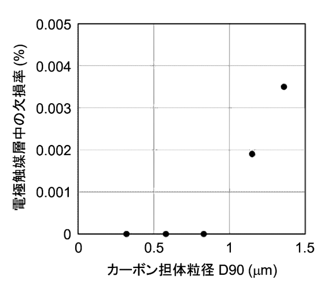
The Figure below illustrates how the particle size (D90) of the carbon support material prepared in step 1 should be below 1 μm if defects in the electrode
catalyst are to be avoided.
Step 2: Preparation of electrode catalyst
The carbon support prepared in step 1 was dispersed in water. Its pH was adjusted to 2 or less with nitric acid, followed by degassing.
Dinitroammineplatinum(II) nitric acid solution and 99.5% ethanol were added.
This mixture was heated at 90°C for 1 h, then filtered.
The resultant solid was air-dried at 100°C for 12 h,
then heat-treated at 300°C in argon, resulting in a 33% mass% Pt-supported carbon support.
Cobalt nitrate and sodium borohydride were added sequentially, and the mixture was stirred for 3 h.
After filtering, the residue was air-dried at 100°C for 12 hours, then heat-treated at 800°C in argon to alloy.
Step 3: Preparation of electrode catalyst ink
The electrode catalyst prepared in the prior step was mixed with water and ethanol (2 : 1 by volume).
Nafion ionomer solution was added, followed by dispersion using an ultrasonic homogenizer.
The product was filtered to get the electrode catalyst ink.
Step 4: Preparation of electrode catalyst layer
Using a squeegee, the catalyst ink prepared in the prior step was applied to a PTFE (polytetrafluoroethylene) substrate sheet and dried at 80°C
for 3 h, aiming for 0.3 mg-Pt/cm2 Pt mass.
Step 5: Production of MEA
Electrode layers from step 4 were placed on either side of a Nafion 117 membrane and hot pressed at 170°C for 300 s to make an MEA.
電極触媒層中の欠損率: defect rate of electrode catalyst layer in the MEA (membrane electrode assembly)
カーボン担体粒径: particle size of the carbon support

This work might reflects significant optimization work, which in turn might be an indication that a similar material configuration and
process sequence might have been up-scaled.
The work illustrates how the particle size distribution of the carbon catalyst support material is critical for reliability.
-
Mica (muscovite, phlogopite, biotite, and lepidolite) was heated in an acid solution to exchange K, Na or Ca with protons. The resulting proton-exchanged
mica was used to build membranes (5-20 μm thickness) and as a component of the catalyst ink in combination with carbon-supported platinum (Pt/C) or platinum alloy (Pt-alloy/C) catalysts.
In the catalyst layers, the mass% ratio of mica powder to catalyst powder varies between 0.4:1 and 1:1.
No electrochemical results are disclosed.
This work illustrates how Bosch considers building membrane electrode assemblies (MEA) based on proton-exchanged mica.
-
Toka Black #3800 (Tokai Carbon, specific surface area: 27 m2/g), PTFE (polytetrafluoroethylene, Polyflon D-210C, Daikin Industries),
the dispersant Triton X-100 (Nacalai Tesque), and water were blended at a ratio of 75:25:150 parts by mass,
producing a microporous layer-forming coating liquid with 23% by mass of indegradable components (carbon fine particles and fluororesin).
Uniformity in the coating liquid composition was ensured using a planetary mixer.
This coating was applied to a conductive porous substrate and dried at 100°C for 10 min,
then heated at 350°C for another 10 min, forming a gas diffusion electrode.
The layer's surface roughness was 6 μm.
The power generation performance of the electrode at 1 A/cm2, used as both anode and cathode,
was 0.58 V, and CRT (cell reversal tolerance) evaluation indicated a retention time of 50 h (time until cell voltage fell below -1.5 V
after switching from hydrogen to nitrogen, 200 mA/cm2).
This work illustrates how the use of Toka Black #3800 from Tokai Carbon in the microporous layer (MPL) of a gas diffusion
layer (GDL) leads to more favorable electrochemical performance as compared to other carbons (from Tokai Carbon, Denka and Cabot).
-
Triweekly patent lists for other categories (Excel files are included for premium users)
-
- Lithium metal containing batteries (excluding Li-S, Li-Air): XLSX
-
- Lithium-ion batteries – electrolytes – liquid: XLSX
-
- Lithium-ion batteries – separators: XLSX
-
- Lithium-sulfur batteries: XLSX
-
- Metal-air batteries: XLSX
-
- Na-ion batteries: XLSX
-
Change your category and patent update preferences.
|