-
Lithium-ion batteries – electrolytes – solid & semi-solid
-
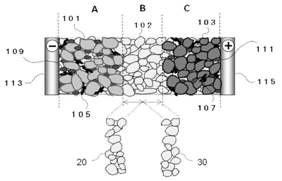
A method for manufacturing solid-state bipolar Li-ion batteries is described (serial stacking of 3 cells),
focusing on preventing resin / carbon-based bipolar layer deformation and detachment during production (see Figures).
For the negative electrode, graphite, sulfide solid electrolyte (SE; Li2S-P2S5),
and polyvinylidene fluoride (PVdF) binder were mixed (58.2 : 39.0 : 2.8 by mass). For the positive
electrode, NCA (LiNi0.8Co0.15Al0.05O2), SE, vapor-grown carbon
fibers (VGCF), and PVdF binder were mixed (84.7 : 13.4 : 1.3 : 0.6 by mass). SE layers were prepared
with acrylonitrile butadiene rubber (ABR) binder (99.4 : 0.6 by mass).
Each resin current collector contains poly(methyl methacrylate) and acetylene black, with interface
layers (≈2.5 μm thickness) formed between the bipolar and active material
layers.
Three single cells were stacked in series and pressed (20 MPa, 30 s, 135°C) with aluminum and
roughened copper foils on the outer layers.
The cycling performance was evaluated between 9.0-12.6 V using a current of 0.522 mA and a cut-off
current of 0.0522 mA for 2 cycles (see bottom Figure, electrode areas not identified in patent).
101: Negative electrode active material
102: Solid electrolyte
103: Positive electrode active material
105, 107: Conductive additives
109, 111: Binders
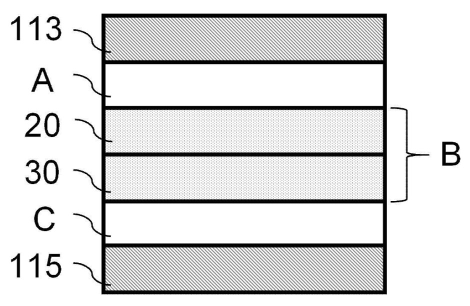
113: Negative electrode current collector (first resin current collector)
115: Positive electrode current collector (second resin current collector)
20: First solid electrolyte layer
30: Second solid electrolyte layer
容量: Capacity
電池電圧: Battery voltage
サイクル目: Cycle number
1サイクル目: 1st cycle
2サイクル目: 2nd cycle
This work illustrates how Toyota Motor is optimizing production of a bipolar cell design in conjunction with all-solid-state sulfide Li-ion batteries
(serial stacking of 3 cells).
Presumably, this kind of cell design with resin / conductive carbon-based bipolar layer might allow for cost-savings and increased energy density also
in other semi-solid or all-solid-state batteries.
-
The premium version includes another two patent discussions, plus an Excel list with 50-100 commercially relevant recent patent families.
-
Lithium-ion batteries – negative electrode (excluding Li metal electrodes)
-
First approach:
Micrometer-sized silicon particles were mixed with ethanol (85 : 15 mass ratio) and wet-milled
using a bead mill (Netzsch) to obtain silicon nanoparticles (D50: 90 nm, Dmax: 150 nm).
B2O3 (2-6 mass% relative to Si) was then added. The dispersion was
spray-dried (180°C) and heat-treated (950°C, N2 atmosphere) to enable boron doping of
the silicon primary particles.
The Figure below shows cycle-life data for half-cells (EC:EMC:DMC = 2:1:7 vol ratio with 1.5 M LiPF6 and 10 mass% FEC)
with various B2O3 addition levels:
Example 3: B2O3 additive (2 mass% relative to Si), exhibits improved
cycle-life
Example 4: B2O3 additive (4 mass% relative to Si), shows further
improvement
Example 5: B2O3 additive (6 mass% relative to Si), highest stability
Comparative Example 1: No B2O3 additive
Separately, in a different second approach, silicon powder was mixed with Al2O3
nanofibers (diameter: ≈600 nm, length: ≥200 μm, Young's modulus: ≥200 GPa) and polyamide-imide
(PAI) polymer in an aqueous slurry with a surfactant. The slurry was coated onto electroplated
copper foil (thickness: 15 μm), calendered (80°C), and pyrolyzed (5°C/min to 650°C, 3 h, under
argon).
In half-cells, these negative electrodes exhibit a first cycle efficiency of 90.0%,
as compared to 89.1% for comparative electrodes without Al2O3. After the
first cycle in full cells with NMC811-based positive electrodes, negative electrodes were analyzed in
terms of expansion in planar X and Y directions (X: 1.10% vs. 1.93% in comparative electrodes; Y: 0.87% vs. 1.65% in comparative electrodes).
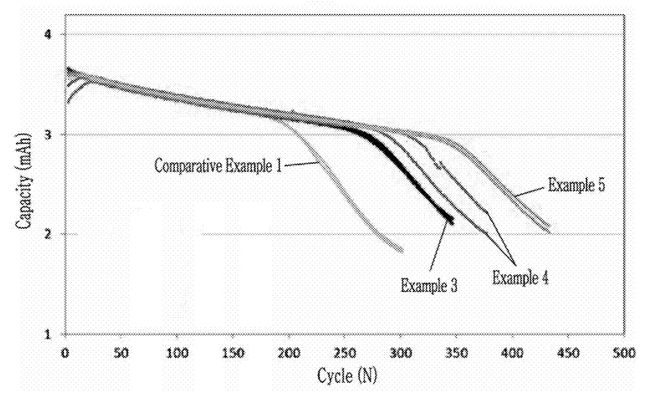
This work illustrates how B-doping of Si nanoparticles leads to improved cycling stability, and that the use of Al2O3
nanofibers in negative electrodes leads to reduced negative electrode dimension change (X- & Y-direction).
-
The premium version includes another two patent discussions, plus an Excel list with 50-100 commercially relevant recent patent families.
-
Lithium-ion batteries – positive electrode
-
A tank reactor was filled with deionized water (55°C) and the pH was adjusted to 8.05 using
sodium hydroxide. A co-precipitation reaction was initiated by feeding an aqueous solution of
Ni and Mn sulfates (1:2 molar ratio, 1.65 mol/kg) and sodium carbonate solution
(27 mass%) in nitrogen atmosphere (0.7 L/min flow rate).
With a continuous feed system, a transition metal carbonate precursor was produced, filtered,
washed, dried (120°C), and sieved. The resulting material was combined with Li2CO3
(Li / transition metal molar ratio: 1.30), heated (930°C, 5 h, gas mix of 20% oxygen and 80%
nitrogen), and sieved through a 32 μm mesh.
A surface coating was applied by dispersing SnSO4 (3.0 mass% with respect to uncoated
positive electrode active material) in deionized water via sonication. The material prepared in
the prior step was added, sonicated further, then stirred (3 h). Water was removed under vacuum
(80°C, 48 h).
The resulting powder underwent thermal treatment: heating (2°C/min to 500°C), maintaining that
temperature (5 h, in air). The end product exhibits a two-layer coating structure: an inner NiO
layer with rock salt structure, and an outer lithium-boron-oxide layer (formed from H3BO3
treatment).
STEM imaging confirms
continuous arrangement of oxygen atoms across the coating interface. As shown in Figure 3,
high-resolution STEM imaging reveals distinct regions of lithium metal composite oxide, first
layer, and second layer, with the oxygen atoms (appearing as relatively bright points) arranged
continuously across the boundaries. The material exhibits a discharge capacity of 240.8 mAh/g
with a capacity retention of 89.7% after 50 cycles (0.5 C charge / 1 C discharge, 25°C).
リチウム金属複合酸化物: Lithium metal composite oxide
第1の層: First layer (NiO with rock salt structure, presumably also contains Sn)
第2の層: Second layer (B-based)

This work illustrates a high-energy LRLO (Li-rich Layered Oxide) active material
with a sophisticated coating in which Ni, Sn, B and crystal phases are carefully distributed near particle surface areas.
-
The premium version includes another two patent discussions, plus an Excel list with 50-100 commercially relevant recent patent families.
-
Fuel cells (PEMFC / SOFC / PAFC / AEMFC) – electrochemically active materials
-
A Laser-induced forward transfer (LIFT)-based method was developed for preparing fuel cell and
electrolyzer catalyst layers. An aqueous dispersion of Nafion® 1100EW ion-conducting polymer
and electrocatalyst (50 mass% Pt/C) was prepared through mechanical agitation and Eiger
milling. The ink exhibits a solids content of ≈25 mass% and viscosity of 400 cP (25°C,
100 s-1).
The cathode catalyst ink was deposited onto a skived PTFE sheet using a HelioSonic (Altana) printing
apparatus. The ink was applied as a 20 μm thick wet layer onto a donor substrate facing the
PTFE acceptor substrate. Laser radiation pulses (70-120 W) were directed through the donor
substrate to transfer ink droplets to predetermined locations to form a uniform catalyst layer.
The deposited layer was heated (100°C, 10 min) to remove residual solvent. The catalyst layer
exhibits an average thickness of 3.5-4.0 μm and a nominal platinum loading of 0.2
mgPt/cm2.
Catalyst-coated ion-conducting membranes were prepared by
transferring the cathode and anode catalyst layers to a commercial reinforced PFSA
ion-conducting membrane (15 μm thickness) through decal transfer (150-200°C). Gas diffusion
layers (Sigracet 22 BB) containing a hydrophobic microporous layer were applied to form
membrane electrode assemblies.
Performance testing at 80°C showed no statistically significant difference between
laser-transferred and conventionally coated layers (see Figure). The laser transfer method enables
significantly faster deposition - less than 1 second for a 100 cm2 area compared to
5-10 seconds for conventional coating.
Example 1 (air): Laser transfer method with air (170 kPa, 80°C, hydrogen / oxygen flow stoichiometry = stoichiometry 2/2)
Example 1 (oxygen): Laser transfer method with pure oxygen (hydrogen / oxygen flow stoichiometry = 2/10)
Comparative Example 1 (air): K-bar coating with air
Comparative Example 1 (oxygen): K-bar coating with pure oxygen
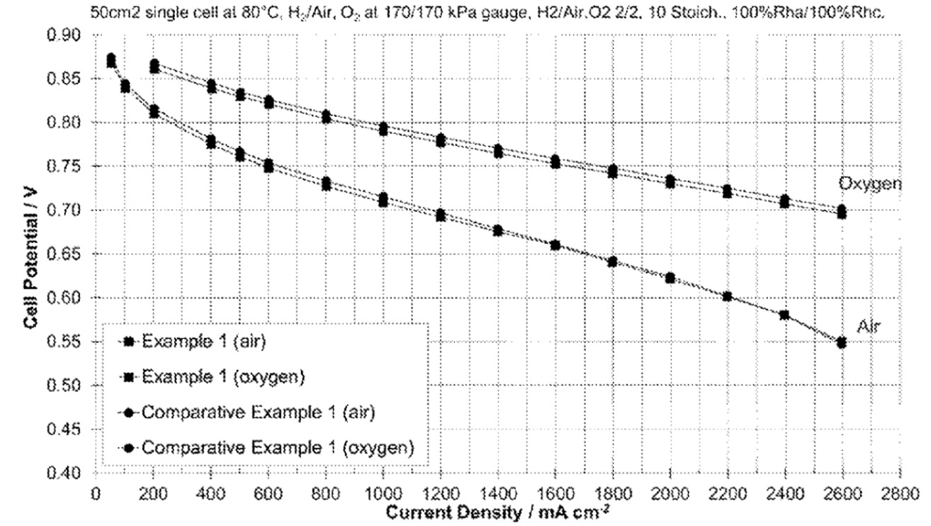
This work illustrates increased process speed through the use of Laser-induced forward transfer (LIFT) for uniform catalyst layer formation on
PTFE sheets.
-
The premium version includes another two patent discussions, plus an Excel list with 50-100 commercially relevant recent patent families.
-
Triweekly patent lists for other categories (Excel files are included for premium users)
-
- Lithium metal batteries (excluding Li-S, Li-Air): XLSX
-
- Lithium-ion batteries – electrolytes – liquid: XLSX
-
- Lithium-ion batteries – separators: XLSX
-
- Lithium-sulfur batteries: XLSX
-
- Metal-air batteries: XLSX
-
- Na-ion batteries: XLSX
-
Prior patent updates
-
2025-02-04
-
2025-01-14
-
2024-12-23
-
2024-12-03
-
2024-11-12
|